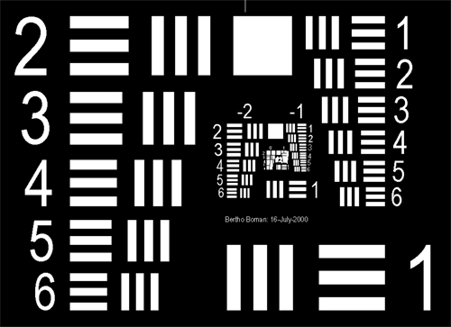
This is a low resolution picture of the test target.
This AutoCAD drawing was created with the correct dimensions
according to the standard. It can be printed either at a 1 to 1 scale or it can
be scaled as required. Many other CAD programs can read AutoCAD drawing files
so try it on your available system. You can select a positive or negative version while printing.
It is based on the old MIL-STD-150A "Military Standard: Photographic Lenses".
Revision "A" was issued 8-Jun-1961.
The files can be downloaded here in both .DWG and .DXF format.
Download USAF-1951.dwg
Download USAF-1951.dxf
The files can also be downloaded via FTP.
FTP site: Vinland.com
User: Public
Pass Word: Public (NOTE: capital P)
Printer Test Lines
For critical line art, PCB layout, and similar applications it is important to know
the basic capabilities of the printer and to have a repeatable pattern
to use when optimizing all the printer variables for best possible result.
Here is a simple test target that has solid color lines in various widths and spaces
from 10 mils down to 1 mil line and 1 mil space.
To avoid all the issues with different graphic formats the target is supplied in the
original standard Gerber RS274X format, and in AutoCAD's .dwg, and .dxf formats.
The actual printing can be done from a Gerber compatible program or from AutoCAD or
clones or many other programs that can import DXF files.
I did a quick printout on an HP 2015dn LaserJet and a practical resolution was
5-6 mil lines and spaces. That agrees with what I was seeing a decade or two ago
when I was making prototype PCBs with photosensitive PCBs. At this time I am
not testing any printers or etching PCBs.
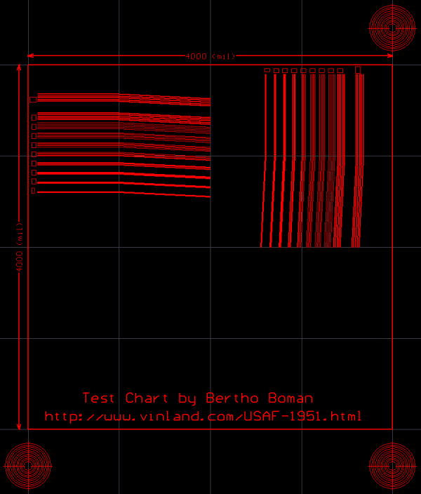
This is a low resolution picture of the Test Lines.
Actually the files are black and white.
Download Test_Lines-0.GTL
Download Test_Lines-1.dwg
Download Test_Lines-1.dxf
The files can also be downloaded via FTP.
FTP site: Vinland.com
User: Public
Password: Public (NOTE: capital P)
Updated Printer Test Lines
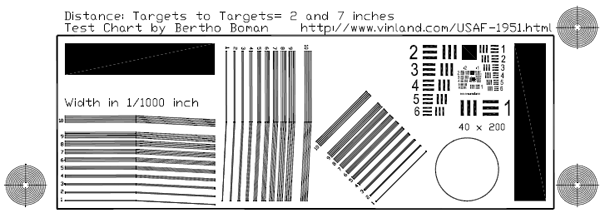
I added the USAF-1951 test chart, density measuring areas and changed the shape to
easier allow multiple printouts on a test page.
This is a low resolution picture of the Test Lines.
The lines are the same sizes as the above chart. The frame is 20 mils.
The largest lines in the USAF target are 40 by 200 mils. The next smaller group is half the size and so on.
To avoid all the issues with different graphic formats the targets are supplied in the
AutoCAD's .dwg, and .dxf formats. I have also included PDF files which were
saved in Acrobat's high resolution mode. Unfortunately I have not had time to
also create a Gerber version but it is on my todo list.
I did some testing on a Canon i9100, HP LaserJet P2015dn and a Lexmark 4975. I am interested in finding
an optimum combination of high print density, no pin holes, and best resolution.
I also used two different Windows printer drivers, so with three printers, plus the extra driver, four different
transparency materials, and varying ink settings, the testing combinations get ridiculous......
I measured the media transmission loss in a clear area and then in a solid test area
and calculated both the absolute transmission loss and the contrast ratio.
This was done on all types of transparencies that I could find. Since it was done with a
spectrometer, I could in some cases see surprising results where prints visually looking darker
were actually worse in the UV spectrum. When I get a little more time I will try to summarize my testing.
I also like to include an Epson printer in the test data but my old Stylus C88+ has a
very clogged print head. I tried to clear it by soaking tissue paper and placing it under the head
without any luck.
I have been reading about disassembling the printer, using cleaning solutions in syringes
to clean out internal tubes and the head but I do not have time to fool around with that.
Test Files:
The PDF version comes with four different offset, 0 - 8 inches.
That allows printing of four test charts with different settings on one page.
The same thing can be achieved when printing from a CAD program by changing the starting vertical offset.
Download Test_Lines-3.dwg
Download Test_Lines-3.dxf
Download PDF with offset=0.0"
Download PDF with offset=2.5"
Download PDF with offset=5.0"
Download PDF with offset=8.0"
The files can also be downloaded via FTP.
FTP site: Vinland.com
User: Public
Password: Public (NOTE: capital P)
I believe the information is accurate but there are no guarantees or liability
accepted for usage of the information.
Bertho Boman
Vinland Corporation
11600 NW 20th Street
Fort Lauderdale
FL 33323
(954) 475-9093
Email: boman33 at vinland dot com
www.vinland.com
|