| Home |
| Misc. |
|
11-August-2018 Bertho Boman |
|
|
|
|
Introduction:
An alternate low-cost and efficient solution:
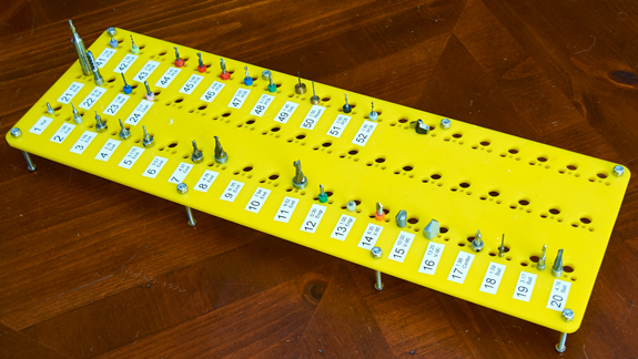
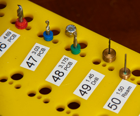
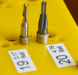
I laser cut the tool holder but of course it can be CNC drill or even manually created. By using the removable labels it is easy to update or change the tooling. In some cases I mounted drill bits in custom tool holders so they can be quickly switched too. By using fixed stops on the individual tools, and keeping track of the tool number, an efficient setup can be achieved that allows fast tool switching without any calibration steps. This type of tool length control is used in the PCB manufacturing with the little colorful rings pushed onto the PCB drills. There are several ways to obtain the stop rings, the PCB drill bit rings are perfect for 1/8 inch tool bits, suitable sized tubular sections are sometimes available, and it is easy to custom make the little rings. The metal ones are typically held in place with Loctite or super glue. The individual tool lengths are entered into the Mach3 or Mach4 tool table or other system used. Tool Length DefinitionThe easy way to visualize the definition of the tool length would be the distance from the top of the ring to the tip of the tool. The tip of the ring is of course the clamped position against the ER-16 collet. Unfortunately that is a very difficult to use surface to calibrate the vertical axis to the top of the table surface or material. Instead a very short tool bit, labeled #0, with a smooth rounded tip is used as a reference and its length is defined as zero. To measure the individual tools, first the #0 reference tool is set to touch the table and the Z-axis set to zero. Then the next tool number is inserted and the Z-axis is adjusted so it just touches the table. The displayed Z- height is the tool length entered into the tool table for that tool. Setting Z-axis EfficientlyBesides using an electronic tool setting option there is a much better way than gradually lowering the tool bit to the table or work piece and sliding papers under it to judge the position. The movement has to be done very carefully and it is too easy to damage bits or work surfaces. A much better way is to reverse the process using a known size diameter round short rod. An ideal one is a tooling pin. Lower the Z-axis quickly to about 7 to 9mm above the table and then try to slide an accurate 10mm rod under the bit. Rise the Z-axis until the rod just slides under the bit. Set the Z-axis to 10mm. It is much faster and much less chance of damages. With a round rod it is easy to feel when it is getting close to sliding under the tool and the Z-axis can then be raised slowly the last few steps. Sliding a flat piece will not give that gradual feel.
Warning
Hopefully, this will help newcomers to this field. Old-timers already know what to do. Bertho Boman
|