How to find a short on a PCB

This procedure is for experienced troubleshooters.
It works with discrete wiring too.

Test Equipment:
• A good Digital Volt Meter (DVM): Ideally it should have microVolt resolution.

• Needle Test Probes: Regular test probes are too crude. Make you own needle probes from old pens using sewing needles soldered on to test wires and then glue/ hotmelt/ epoxy the needles and wires into the empty pen shells. They will look like regular test probes except the tip will be a sewing needle and very sharp. It will be able to penetrate the solder resist coating on the PCB traces. Do not blame me when they fall off the workbench and get stuck in your leg. Be careful.

• Power Source: Use an adjustable power supply or other power source to have a continuous current into the PCB but not so large that something will be damaged.

Testing: Continue reading

Printer Heated Bed Design & Measurements

It is very desirable to have a heated build platform and unfortunately the Ultimaker does not have one.  Therefore users have to improvise their own versions.  Basically there are two common ways to provide the heat but as usual there are exceptions.  Typically the heaters are used to heat a glass plate that acts as the built platform.  The big advantage is that it is easy to get a flat glass plate and it can easily be cleaned off without worrying about damaging the original acrylic plate and tapes. Continue reading

Avoiding Nozzle Leaks

A common problem is plastic leaking around the nozzle.  Different websites and Wikis suggest to use Teflon tape on the threads for sealing.  That should not be needed if the parts are properly made.  The Ultimaker nozzle and brass heater barrel that I received are very well-made.

There are only two locations that can leak:  Each end of the brass barrel.  Threads do not leak, that is a symptom of a failed seal at the barrel tip. Continue reading

Dissolving PLA

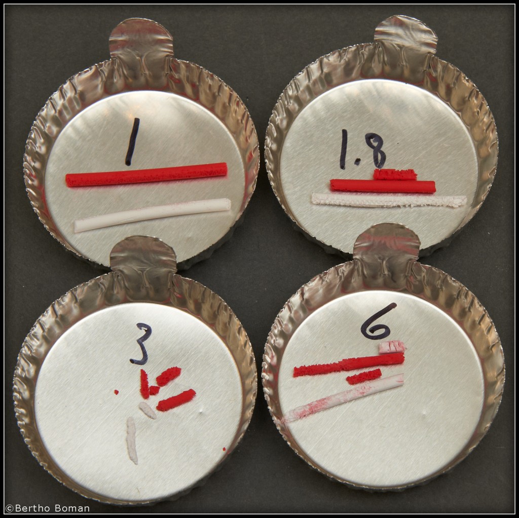
PLA is a very common plastic used for 3D printing.  I have been trying to find off-the-shelf products to dissolve PLA both for just cleaning it off hardware and for removing it if the PLA is used as support material.

My first goal is to find an easy way to remove PLA from nozzles, barrels and so on so they can be assembled cold without fighting with PLA residues. Please remember that we are considering two processes:

A: How to remove PLA from metal parts.

B: Dissolving PLA and leaving ABS untouched.

As for safety,should be reasonably safe when removing PLA by putting the small metal pieces in a glass jar with the chemical and cover with a lid and afterwards fishing out the pieces with tweezers or tongs .

When removing large amount of PLA support structures it will be much more critical to have a safe liquid since normally there will be relatively big objects to treat.
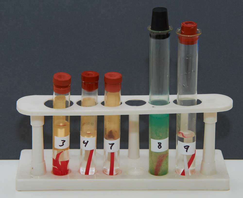
I tested: Continue reading

3D Scanning

This is the companion entry to the previous 3D probing one.  There are many free and low-cost software solutions to optical scanners.  Commercial scanners range from thousands of dollars to hundred thousand or so.

One very excellent low-cost ( about $200) program is called David’s Laser Scanner. The links are include in the write-up below together with free conversion software.  Actually the best way today is to use a projector and project different patterns on the object to measure under the program’s control and in a few seconds a very good 3D copy is created.  Look for articles on “Structured Light”.    Spend some time on David’s website and see the result of user-submitted scanned objects.
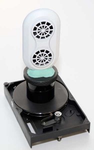
http://www.vinland.com/Turn-Table.html

3D Probing

To duplicate an object it is sometimes necessary to accurately measure it.  There are basically two directions to go: To measure point by point with a digital probe or other point measuring device or to use an optical scanner to obtain the desired information.

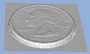
The digital probe requires a CNC system that is used to obtain point by point data measurements.  When the highest accuracy is needed that is the way to go.  Commercial probes are very expensive, many thousands of dollars.  Here is a link to how to make your own and the software to convert the measured data.
www.vinland.com/Touch-Probe.html


Extruder Drive Upgrade

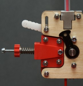
The mechanism that feeds the filament into the extruder basically consists of a stepper motor that through a gear turns a knurled bolt.  Th filament is pressed against the the knurled bolt and as the bolt turns the filament is forced into the Bowden tube.  Although it works and many users do not have a problem I and many others have said many bad words about it.  A search on user-groups and Thingiverse will show up multiple fixes and replacements for the drive.  After analyzing the problems I came up with a good improvement that is easy to implement and the printer can even make the improved parts by itself.  There are basically three problems:

1:  The knurled drive bolt is marginal.  Ultimaker recently upgraded it from V2 to V3 but I like to see an even better bolt with “proper” teeth cut instead of using a knurling tool.

2:  The filament is pressed against the bolt by a stationary piece of plastic.  Although it is made from Delrin there is unnecessary friction since the force pressing the filament is rather large.

3:  The position of the pressing plastic is fixed so there is drastic variation in the pressing force for slight dimensional changes of the filament.

The solution that I came up with addresses the last two items and it makes a drastic improvement.  Here is a link to the details:

http://www.vinland.com/UM_Extruder_Bearing.html

I also placed all the files on Thingiverse to make it easy for others to duplicate it:

http://www.thingiverse.com/thing:26094

FDA Approval!!

We are extremely happy since we just received FDA (USA Food & Drug Administration) and CE approval on a medical device that Vinland designed and is manufacturing for a customer.  It took over a year of different agencies testing the device, quality approval of Vinland to manufacture the device, and at the end about 950 pages of documentation.  The device is an electro-surgical device that is using high frequency high voltage pulses to cut or destroy tissue.

This also relates to 3D printing since it is one reason why I keep pushing to have the different printing software to provide options to properly document how a print was made so it can be duplicated.

Bowden Tube Fixes

The used filament is is driven by a stepper motor and fed through a rather stiff but flexible “Teflon” tube, called a Bowden tube, to the extruder section where the filament is melted and then dispensed as a very thin melted string.  It is a clever idea since it reduces the mass at the moving “head” and allows faster acceleration.  It also comes with drawbacks:  The mounting method at both ends are not good and many users report problems because of that. Continue reading

Heated Build Platform “Bed”

The next item to change was the build platform.  The standard one is an Acrylic plate covered by  masking tape and I really dislike it.  The bed adjustment screws also needed an improvement.   There are two basic ways to add a heated bed:

1. Use low voltage high current heater.  It is usually an etched pattern on a PCB and an external high current DC power supply.

2. Use a mains operated heater and no separate high current power supply is needed.  Of course working with mains has additional risks but so does wiring a high current power supply that also needs to be connected to the mains.

I obtained a boro-silicate glass plate of the correct size and since I already had 120V heating pads that can be attached by a high temperature adhesive, I attached them to a matching size aluminum plate to evenly spread the heat since glass has poor heat conduction.  I added a thermocouple sensor to the glass itself and the heaters are controlled by a commercial digital PID controller that I also happened to have.

After adding new mounting and leveling screws I am now very happy with that section.

Home Sensor & Limit Modifications

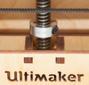
One of the first thing I did was adding a mechanical limit to the Z-stage.  The  X & Y motors with the belts are not strong enough to cause any damage if hitting the mechanical limits.  I do worry about the Z axis causing damage since it has the screw pitch advantage for added force.  For safety I added a clamp on the lead screw that
creates a safe limit if everything else fails. See Picture:

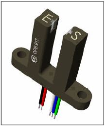
For accurate zeroing I added an opto-interrupter that is repeatable to a few microns, much better than the stability of the wood frame and table mounting.

See: http://www.vinland.com/Opto-Interrupter.html

I have the opto set so it triggers about a mm above the table so I never need to worry about hitting the table.  I have in the software turned off the limit switches and only use them for homing.

Then in the startup code  I have:
G28 X0 Y0                 ;move X/Y to min end stops
G28 Z0                    ;move Z to min end stops 
G92 X0 Y0 Z0.95 E0        ;reset software position to front/left/z=0.0

Tweaking the Z value will allow fine adjustment of the table without trying to fiddle with moving microswitches around.

3D Printer Startup

March-2012: I was too busy to start building the printer at once but once I started it was easy to put together since the kit is well-made.

The software and usage instruction were not so good but the user group support is great and I highly recommend to use the open source software for slicing and controlling the printer.  The links are below.

Make sure to start with the excellent Cura to make the initial learning curve as easy as possible.

Personally I like full control so I do the slicing, scaling and preparation separately on my main desktop and then save the G-Code file on a server.  Then I use the “Printrun” program on a dedicated small PC to run the printer.

Ultimaker forum and wiki: www.Ultimaker.com
Slicing software and Printrun: http://daid.github.com/Cura/
Google User group: ultimaker@googlegroups.com