Introduction:
I have a Taig DSLS 3000 CNC milling machine that needed home switches. I have been planning to put really accurate optical sensors on it for a long time.
See: http://www.vinland.com/
Opto-Interrupter.html
but I never have had enough time to do that. Eventually I got fed up and put some regular micro switches on the mill as a temporary solution. There are many ways to do it but here is what I did. Hopefully this information will help others to also add switches on their equipment
Design Concept:
My goal was a quick and easy way to reliably put the switches on the mill with a minimum of drilling and machining. I especially wanted to keep the modifications of the mill itself to a minimum.
Z-Axis:
This is just a plate with four holes using the existing mounting screws. The switch is positioned so it triggers just before the vertically slide hits the mechanical end position. That way it can never damage the switch or change the home position if I accidentally jog it into the mechanical end position. The holes are slightly oversized to allow for a small amount of adjustment.
Y-Axis:
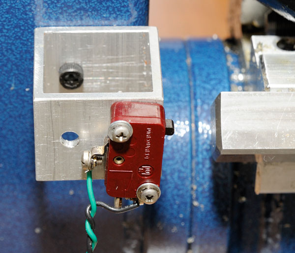
In this case I did not see an easy and accurate way to use existing screws or mounting holes so I drilled and tapped a #10-32 hole and used a small section of 33 x 33mm aluminum tubing to mount the switch. There is an extra hole for inserting an "Allen" wrench. The switch is activated by the slide itself near the end position as described above.
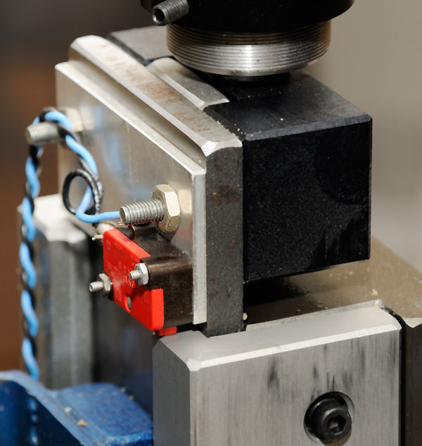
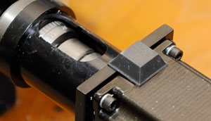
X-Axis:
I removed the rubber way cover and inserted set screws in the holes. They in turn were used to hold the bracket for the micro switch. The bracket was made by cutting off a section from a 25 x 25mm aluminum bracket and then mounting the switch at the end. The switch is being activated by the little round stand-off seen on the left in the picture. It is held in place by a nut in the table slot and a screw. That makes it easy to adjust it and no modifications are needed to the mill.
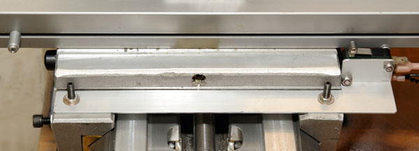
Way Cover:
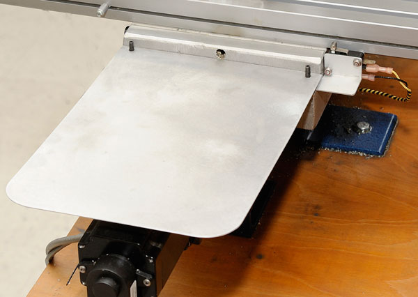
This turned out very well: I got rid of the rubber way cover and at the same time got a switch mount. I made a simple rectangular piece of aluminum that hooks on to the two screws and the other end rests on the motor. I am very happy with this solution since I really do not like the rubber protective covers. This is nice and clean and I can just lift it off to clean and lubricate the ways. Actually the plate rests on a little rubber bumper on top of the motor to avoid a rattling sound. See: the picture below.
Unfortunately I have not found a good solution yet for replacing the rear way cover. If anyone has a suggestion I like to know it.
Next Step
If the switches are going to be left in these positions they should have some protective covers mounted to keep then clean. My goal is to replace them with the optical sensors when I get some spare time. I will of course replace the temporary wiring with properly done connectors and support.
Bertho Boman
Vinland Corporation
Fort Lauderdale
Florida USA
(954) 475-9093
Email: boman33 at vinland dot com
www.vinland.com
|