| Home |
| Misc. |
|
29-Feb-2016 Bertho Boman |
|
|
|
Introduction
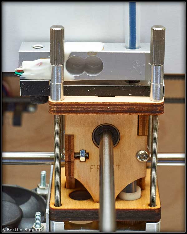
Loadcell Mounting
That end of the loadcell has the mounting hole enlarged and threaded for 1/4"-28. The finer thread, 28, instead of the standard 20 threads/inch will not cut deeply into the Bowden tube. The Bowden tube has a matching thread. Note: The Bowden tube ends in the loadcell. The driving end of the Bowden tube is similarly constrained in the extruder. I have been using this type of mounting for several years without any problems and it is very solid without any movement in the joints. 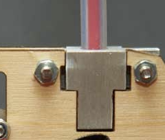
Bowden Drive End Mounting Block There is a short piece of Bowden tube that is going into the extruder head as normal and the filament is entering the extruder "hot end" as before. By cutting the Bowden tube as described, I am able to measure the actual force on the filament being pushed into the melting chamber. Force Display
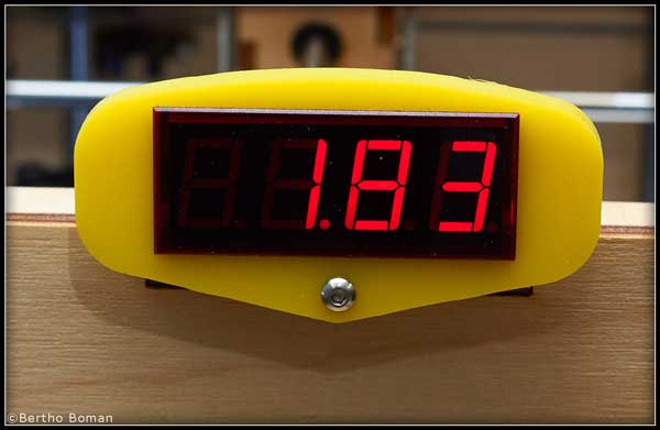
The 7-Segment Display The display is actually a self-contained digital voltmeter that measures 0 to 200mV and shows the result on the 7-segment displays. It is separately powered by a 5V adapter. There are many similar displays, both LED and LCD, available on eBay and regular distributors like Digikey. The display is mounted in a laser cut frame which is attached to the front of the Ultimaker. Electronic Information
I wanted the force measurement to be self-contained so I needed an analog signal that could be interfaced to the analog measurement display. The output signal from a loadcell is a very low voltage, just a millivolt or two so the signal needs to be amplified before connecting the signal to the voltmeter display. I am using a custom amplifier that I designed for a customer and it was a great match for this application. 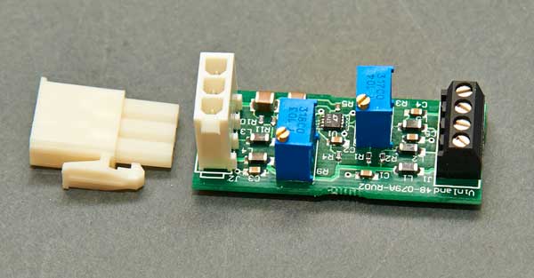
Vinland's Custom Bridge Amplifier Summary
For more 3D printer information and electronic troubleshooting see Vinland's blog:
www.Vinland.com/blog
Bertho Boman
|